
SNES 1CHIP SNESRGB Installation
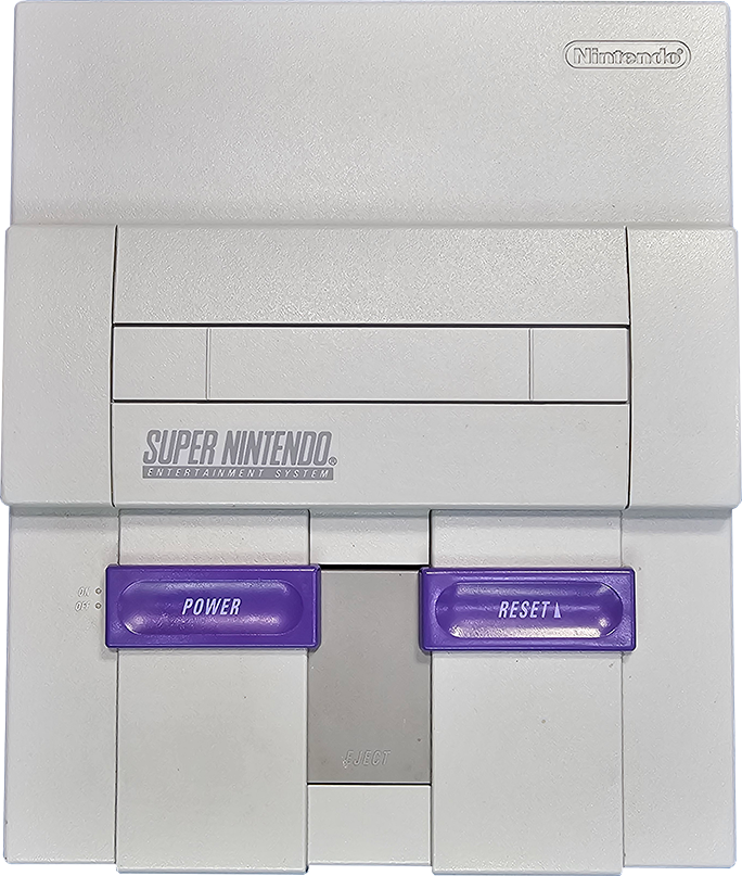
SNES “1CHIP” Console
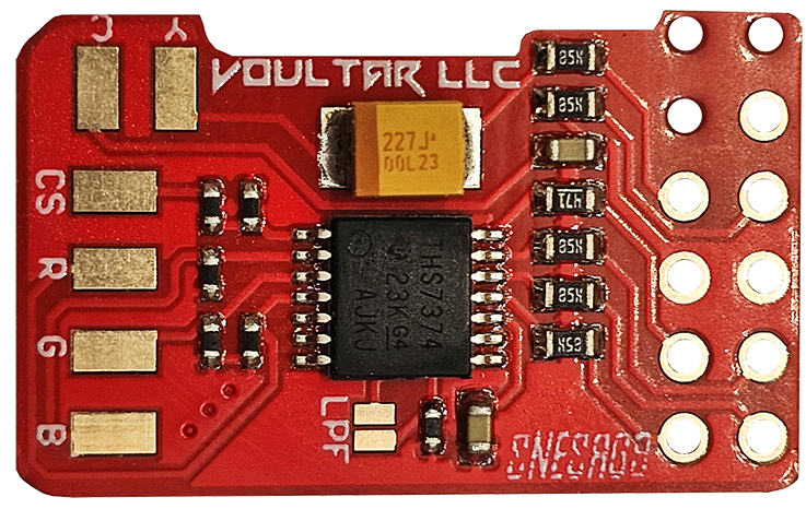
SNESRGB Kit
This page will guide you through the procedure of installing the SNESRGB kit for the SNES 1CHIP console. The SNESRGB kit replaces the RGB(S) output, yielding properly attenuated video levels and an incredibly sharp reference quality video signal. With the exception of the casings, the Super Famicom is identical to the SNES, making this document largely applicable to owners of 1CHIP Japanese systems. PAL consoles are NOT supported. You can purchase the SNESRGB kit from my store.
Follow the directions below and have a great time modding!
Before We Begin...
The SNESRGB kit is only compatible with the SNES (SNS-101) Mini and SNES 1CHIP revisions.
This kit WILL NOT WORK with any other SNES console revision.
SNES 1CHIP Identification
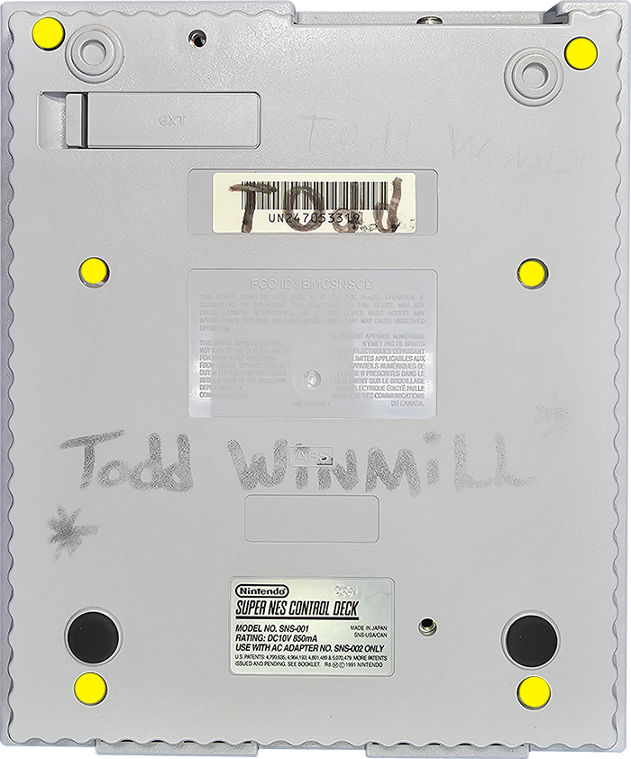
Only later released SNES systems have “1CHIP” mainboards. Systems with a serial number beginning with “UN3” are likely to be a 1CHIP revision. However, you won't definitively know until you open the system up and inspect the mainboard.
1CHIP systems will have “1CHIP-01”, “1CHIP-02”, or “1CHIP-03” in the bottom corner. See below:
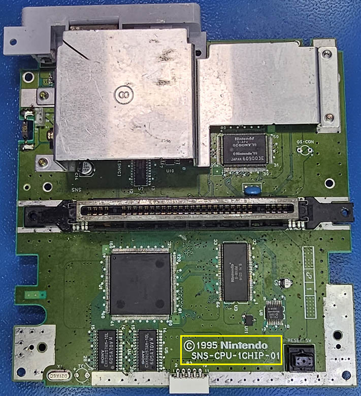
You MUST disassemble your console to verify your SNES revision!
The serial number alone is NOT definitive!
Tools Required
- Soldering Station
- Phillips Screwdriver
- 4.5mm Game Security Bit
Disassembly
Flip the console over and extract the (6) 4.5mm game-bit security screws. Remove the top shell.
Turn the power switch on to de-energize the system and then remove these 2 screws.
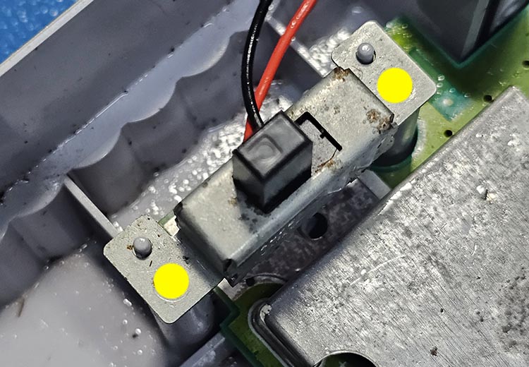
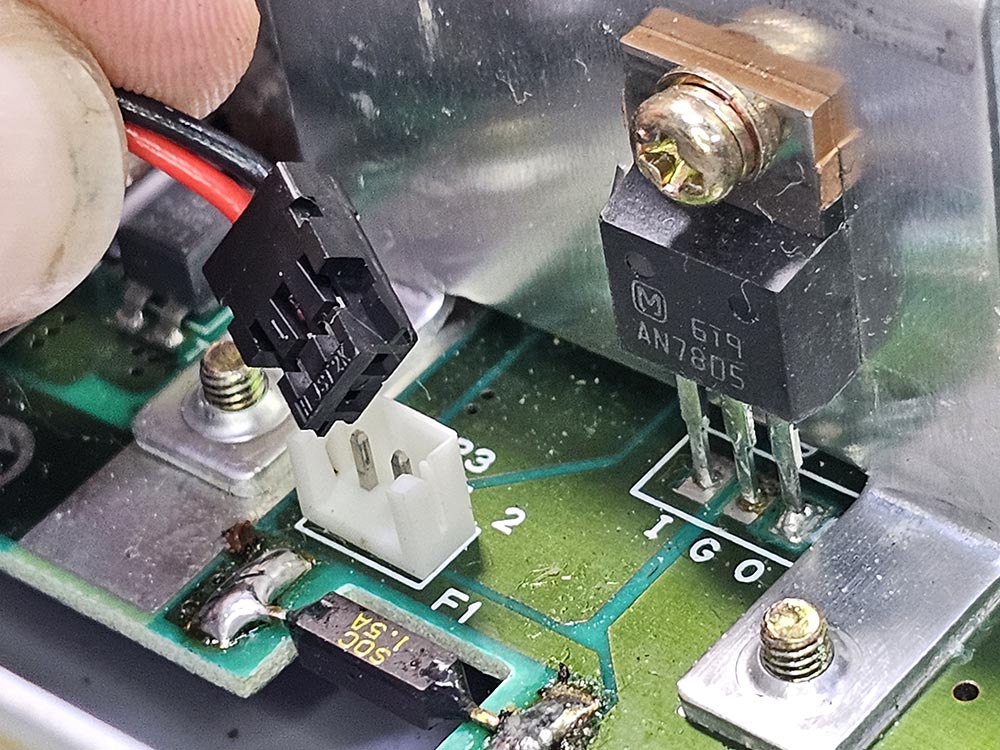
Unplug the power switch loom from the SNES mainboard.
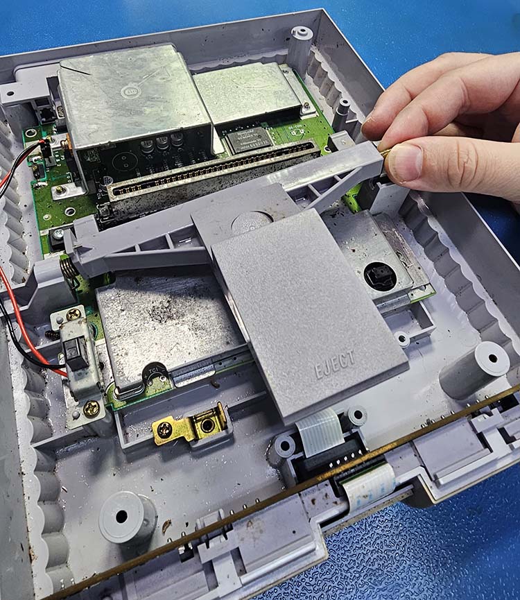
Carefully lift the metal rod and pull away to decouple the eject mechanism. Watch the spring!
Remove all of the screws marked in yellow and blue to extract the mainboard.
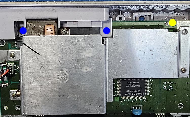
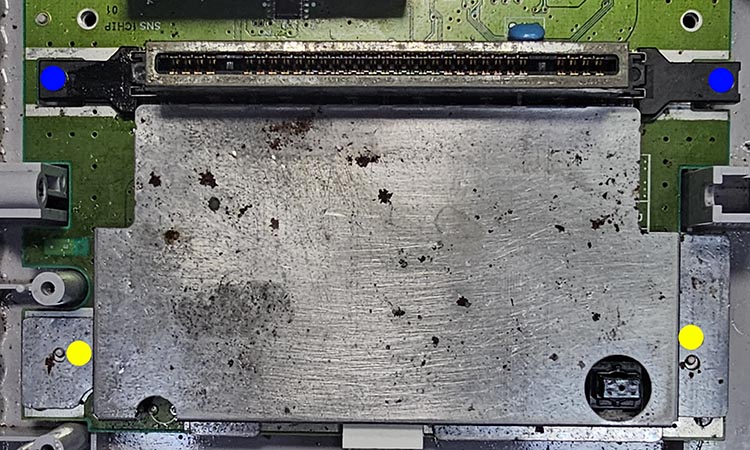
Don't mix up the screws marked in blue with those marked in yellow!
SNESRGB Kit Prep
Depending on your 1CHIP revision, the RGB circuitry must be disabled by removing 3 or 4 components. Please note that 1CHIP-01 and 1CHIP-02 revisions already output C-Sync to the multi-out, making our job easier.
The 1CHIP-03 revision does NOT output C-Sync.
C-Sync can be restored via the SNESRGB kit.
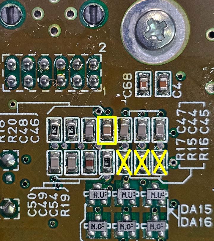
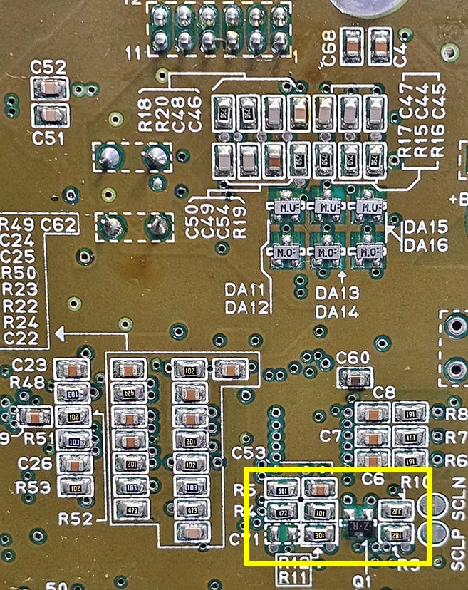
Remove the 3 resistors marked with “X”. The capacitor inside the yellow square is for C-Sync and should only be removed if you want to buffer C-Sync through the SNESRGB kit. Because the 1CHIP-03 doesn't output C-Sync, this capacitor will be missing from the mainboard.
See the images below:
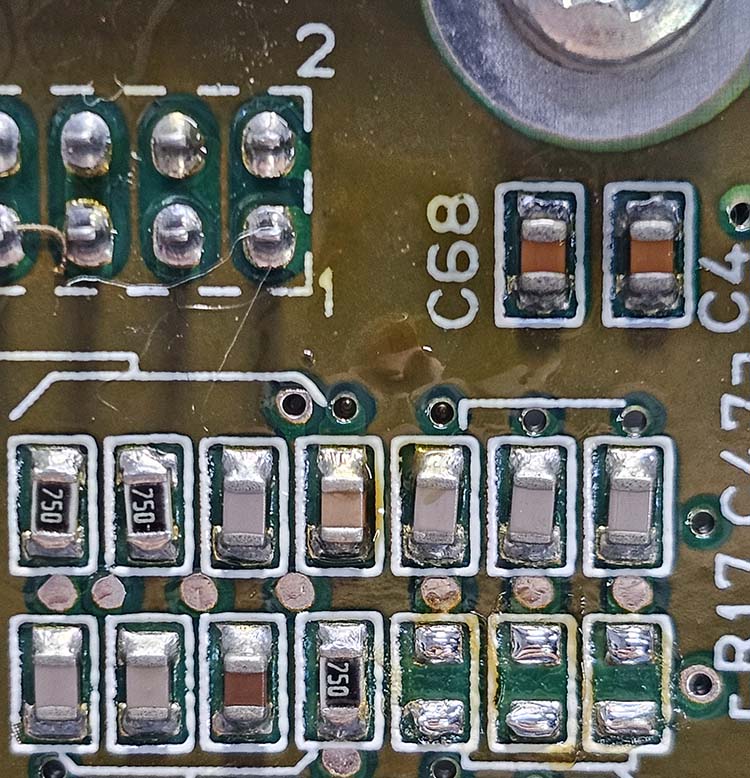
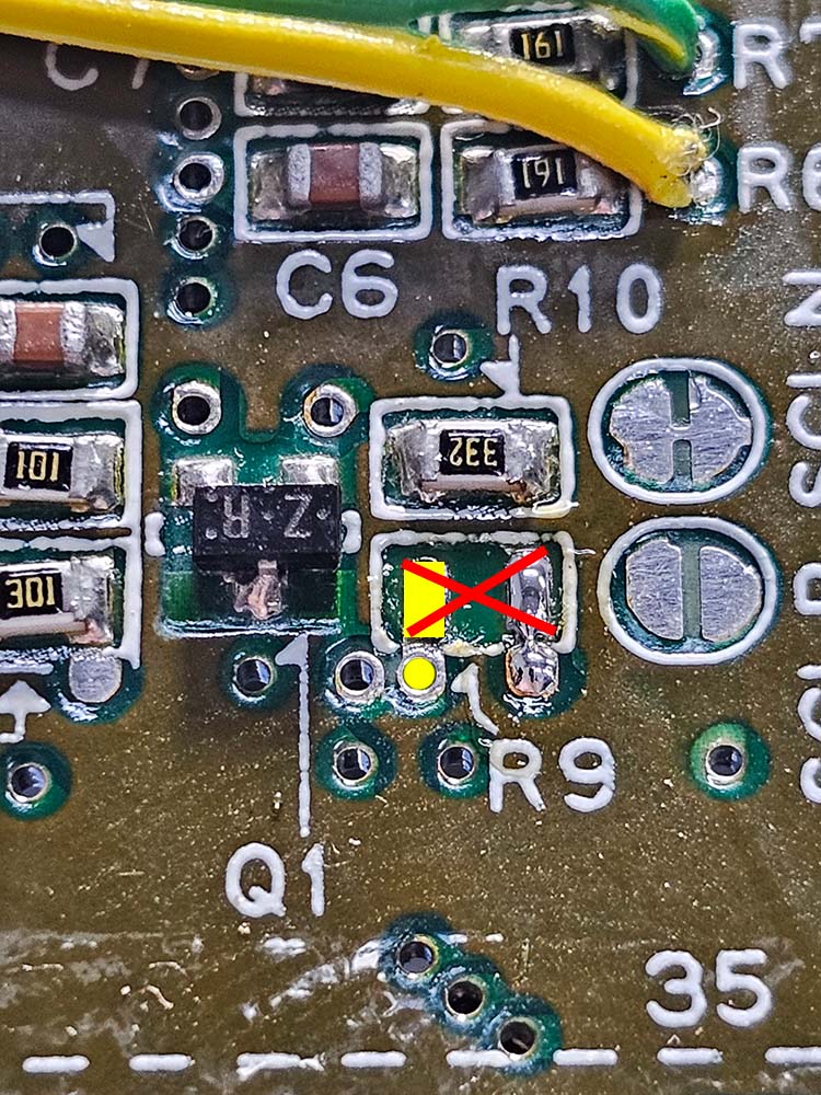
This is how it should look if you have a 1CHIP-01/02 and you want to leave the C-Sync as it is:
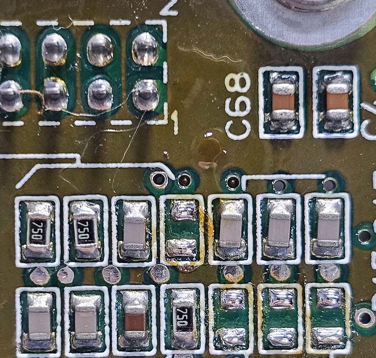
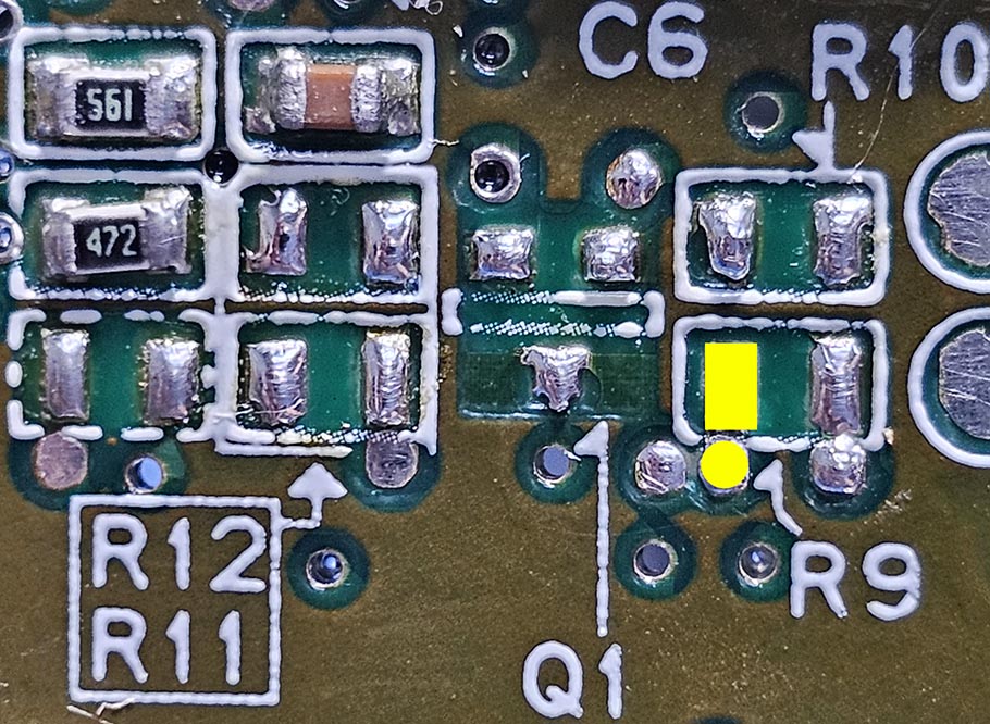
This is how it should look if you have a 1CHIP-03 or if you want to buffer C-Sync through the SNESRGB:
The only benefit of using the SNESRGB to buffer C-Sync is to conform the signal to a safe voltage level, regardless of the type of C-Sync cable that you use. However, C-Sync that's generated by the SNES is a TTL signal that will need to be attenuated with a series resistor (usually in the cable with a value of 470Ω), to make the voltage level safe for devices, downstream.
SNESRGB Kit Installation
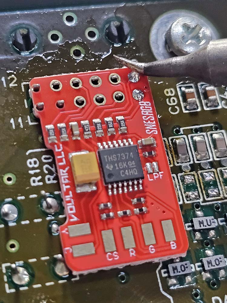
Place the SNESRGB kit over the multi-out pins of the SNES 1CHIP mainboard.
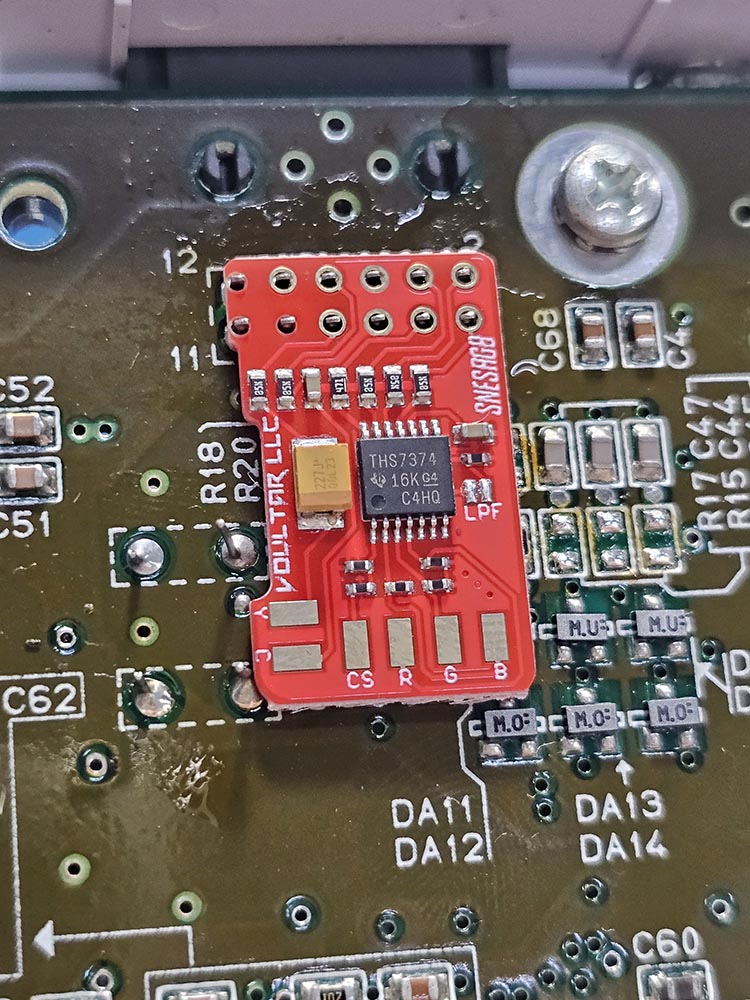
Solder the SNESRGB kit to the multi-out pins.
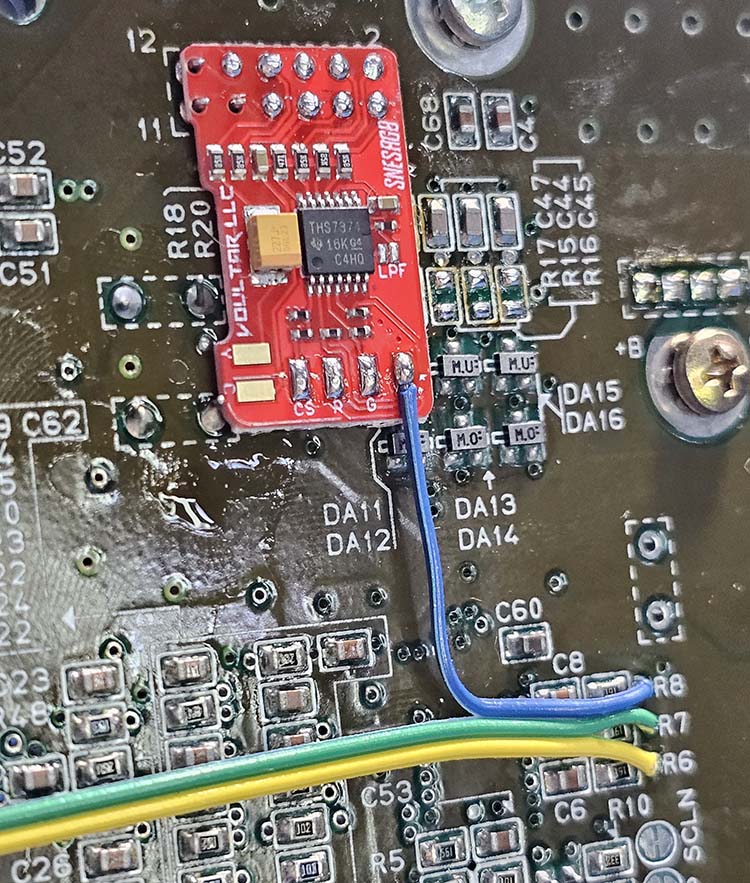
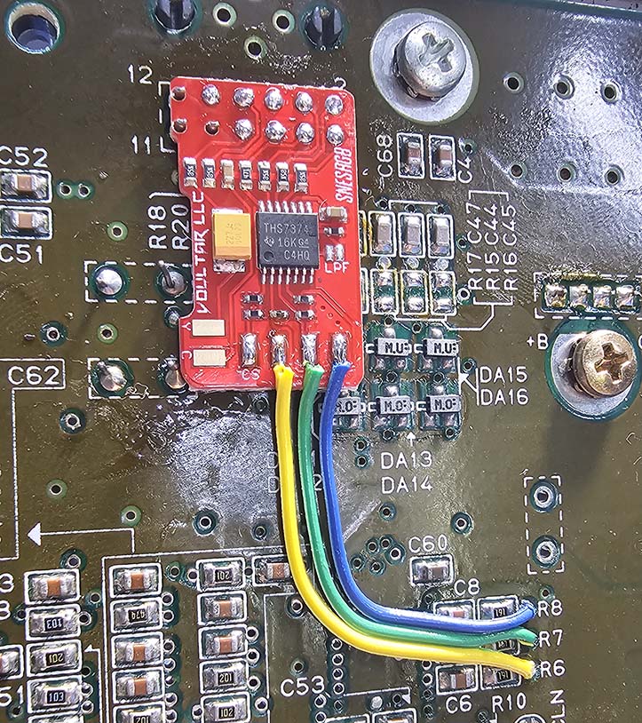
With all of the pins soldered, your SNESRGB kit should now look similar to this:
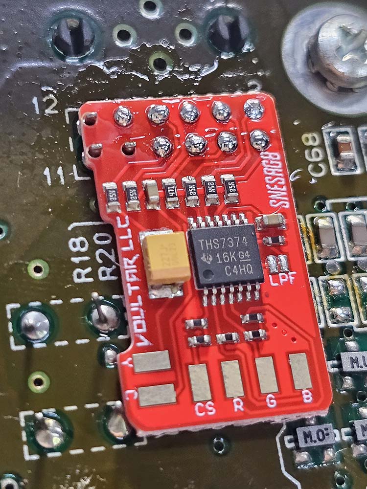
Prep the SNESRGB kit by tinning the c-sync, red, green, and blue solder pads.
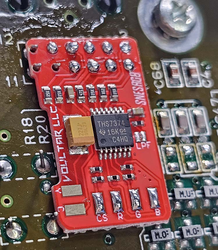
It is NOT necessary to insulate the bottom of the SNESRGB kit!
Wire Preparation
Strip and pre-tin 4 conductors for: c-sync, red, green, and blue.
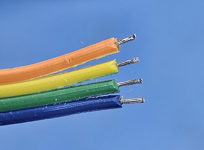
Keep the pre-tinned conductor length no longer than 3mm!
SNES Solder Points
The RGB signals are located in the area marked in yellow.
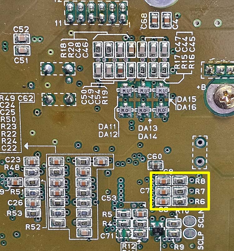
Each color signal has 3 different locations that you can tap:
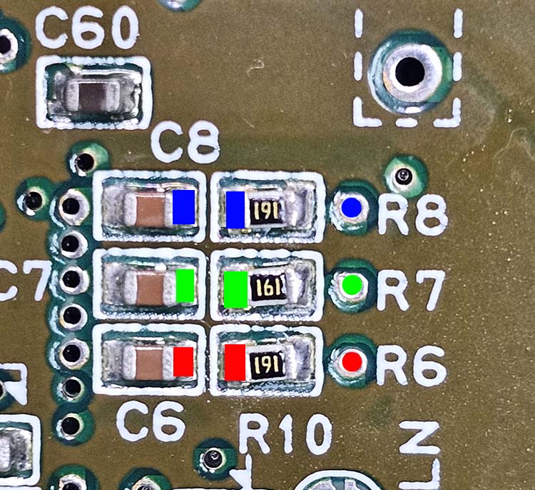
In this example, we'll solder directly into the vias: R6, R7, and R8.
SNES Composite Sync
If you have a 1CHIP-01 or 1CHIP 02 and want to leave C-Sync as is, you may skip this section. However, if you have a 1CHIP-03 revision or you want the SNESRGB to buffer C-Sync regardless of the revision, continue reading this section.
The C-Sync components are located in the section of the mainboard marked in yellow:
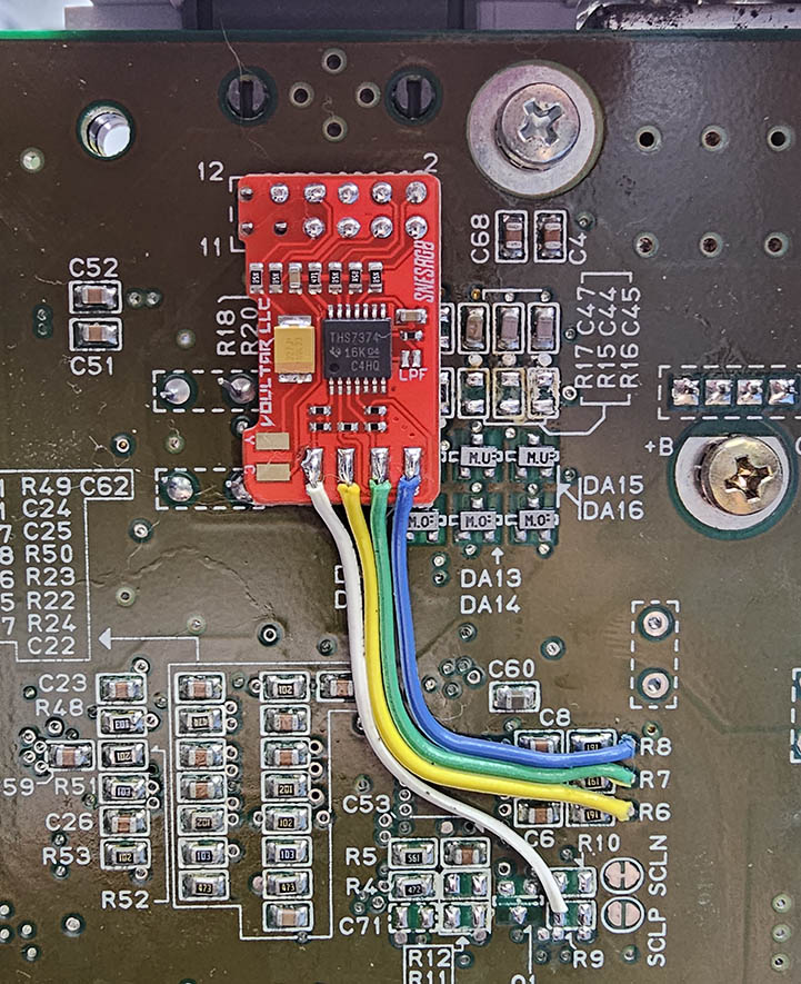
If you have a 1CHIP-01 or 1CHIP-02, remove R9 and solder a conductor to either area marked in yellow:
1CHIP-03 systems aren't equipped with C-Sync. Solder a conductor to either area marked in yellow:
SNESRGB Kit Soldering
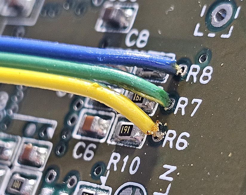
Carefully measure the conductors and cut them to the appropriate length.
Solder each conductor to the corresponding pad on the SNESRGB kit.
Finally, solder the C-Sync connection and your installation will be complete.
The “LPF” jumper on the SNESRGB kit will enable a low-pass filter when bridged.
This is useful when the downstream device doesn't properly filter out high frequency content!
Ghosting Fix
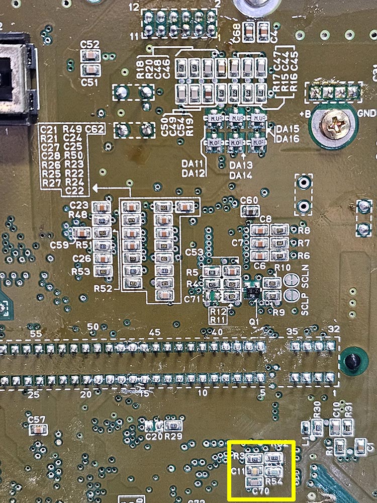
After analyzing the DAC of the 1CHIP, I found a way to greatly minimize ghosting that might be seen in solid backgrounds. Shipped with your SNESRGB kit is an (optional) 220nF capacitor that installs into location C11 on the mainboard.
The location for C11 is within the area marked in yellow:
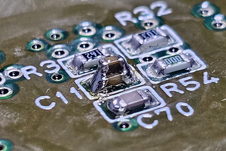
You can stack the new cap on top of the existing C11 cap!
(See picture below)
Newly installed capacitor stacked over C11:
Finishing Up
Congratulations on your installation! Please be sure to check over all of your soldering and ensure that your work is clean.
Test your system and all video outputs prior to reassembly. Remember to pay attention to those screws!
Troubleshooting
“I have no video.”
- Does composite video still work?
- Are you using the appropriate cable?
- Are you using C-Sync? Did you connect it properly?
- Do you have audio?
- Did you keep the pre-tinned conductors for the vias short?
- Is your solder work clean? Any cold joints or bridging?
“I have video but I'm missing a color or the color is wrong.”
- Did you solder the connections correctly to the SNESRGB kit?
- Did you solder the connections correctly to the SNES Mini?
Disclaimer
The information on this website is provided as is without any guarantees or warranty. In association with the product, Voultar LLC makes no warranties of any kind, either expressed or implied, including but not limited to warranties of merchantability, operational failure and/or damage as a result of end-user installation. Use of this documentation by a user is at the user’s risk.