Table of Contents
SHVC-CPU-01 Edge-Enhancer Installation

This page will guide you through the procedure of installing the SNES Edge-Enhancer kit into the SHVC-CPU-01 SNES/SFC revision. The SNES Edge Enhancer is an edge correction modification that “deblurs” the video output, yielding much sharper pixels without sacrificing video quality. The SNES Edge-Enhancer is also a dedicated video recovery appliance that preserves and improves all video outputs. Electrically, the Super Famicom is identical to the SNES, making these instructions applicable to the NTSC-J (Japan) equivalent. You can purchase the SNES Edge-Enhancer kit from my online shop.
Follow the directions below and have a great time modding!
Before We Begin...
The SNES Edge-Enhancer is ONLY compatible with 2CHIP systems.
This kit WILL NOT WORK with 1CHIP systems.
It is advised to test the SNES with the SNES Burn-In Test Cartridge ROM to ensure all chips are working properly.
SNES Mainboard Identification
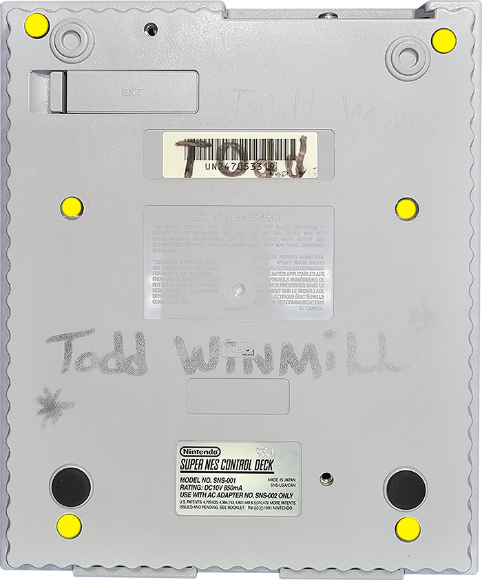
The mainboard revision of the SNES can only be definitively identified by disassembling the unit. The serial number found on the bottom of the console isn't a reliable way of identifying revisions.
The mainboard revision is silk-screened on the bottom right-hand corner. See below:
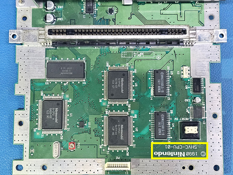
You MUST disassemble your console to verify your SNES revision!
The serial number alone is NOT definitive!
Cap Kit Installation (optional)
If you've purchased a cap kit along with your Edge-Enhancer, please follow the cap-kit installation guide before moving forward with the main installation.
Materials Required
- Soldering Station
- Hot Air Rework Station (optional)
- Phillips Screwdriver
- 4.5mm Game Security Bit
- 26-28AWG Stranded Wire
Disassembly
Flip the console over and extract the (6) 4.5mm game-bit security screws. Remove the top shell.
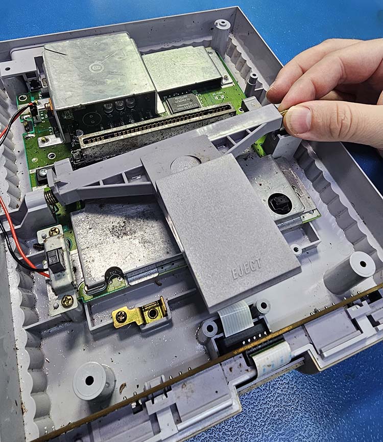
Turn the power switch on to de-energize the system and then remove these 2 screws.
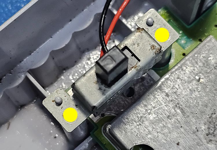
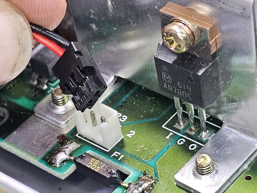
Unplug the power switch loom from the SNES mainboard.
Carefully lift the metal rod and pull away to decouple the eject mechanism. Watch the spring!
Remove all of the screws marked in yellow and blue to extract the mainboard.
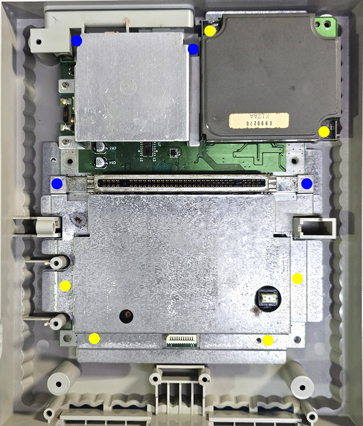
Don't forget about the screw found underneath the sound module.
Don't mix up the screws marked in blue with those marked in yellow!
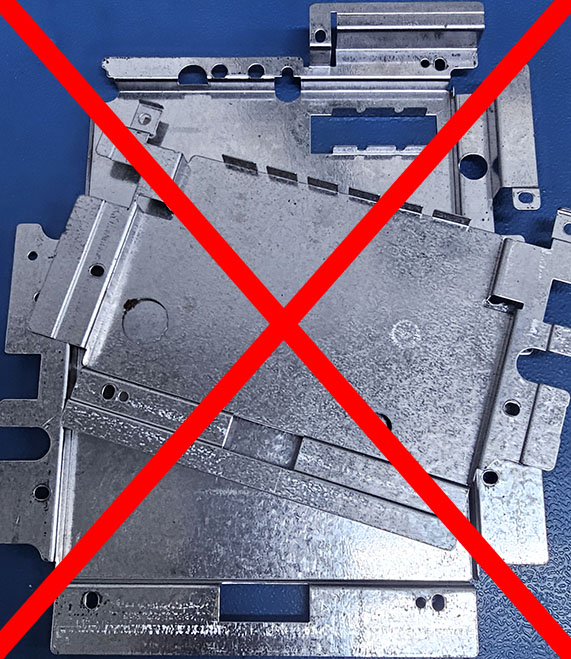
Do NOT reinstall the top/bottom RF shielding (not including heatsink) during reassembly. Discard ALL RF shielding and do NOT use them as they generate noise.
SNES Mainboard Preparation
The RGB circuitry must be disabled by removing a series of components. This can be accomplished by either flooding solder onto the components with a soldering iron or by using a hot air rework station.
Be sure you're following the directions for your specific mainboard revision!
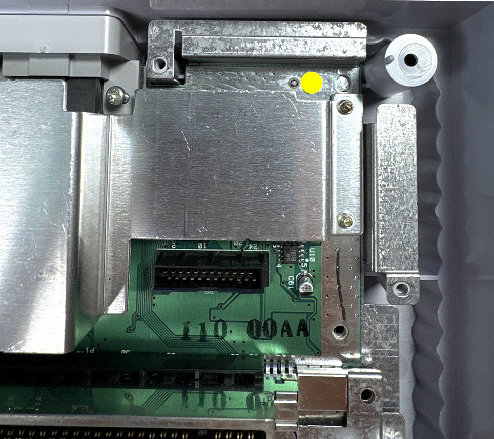
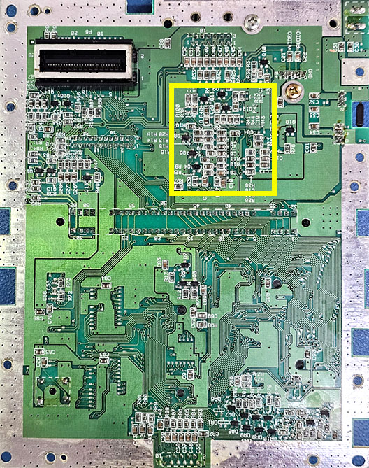
We'll be working in the area within the yellow box:
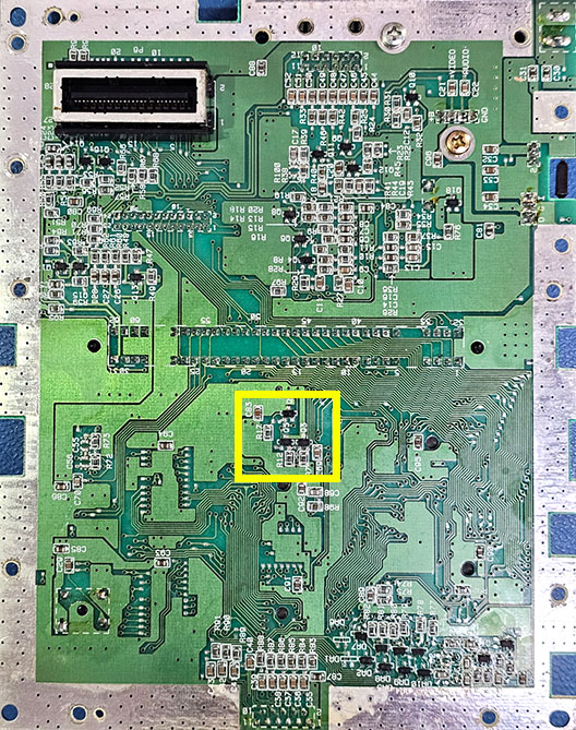
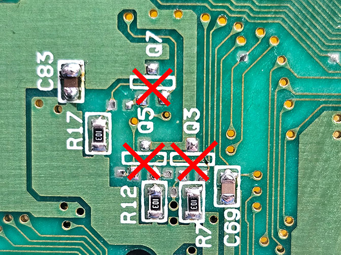
Remove the components: Q3, Q5, and Q7.
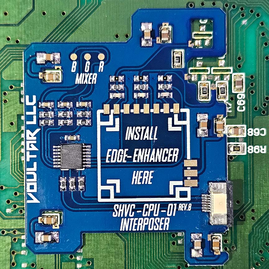
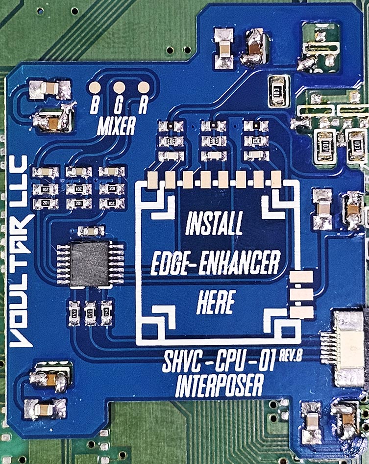
Align the SNS-CPU-01 interposer as shown:
The castellated edges of the interposers should look similar to this prior to soldering:
Ensure that the solder locations marked in yellow are approximately aligned.
Solder a single point to hold the interposer in place and make minor fitment corrections!
Solder all of the castellated edges of the interposer to the SNES mainboard.
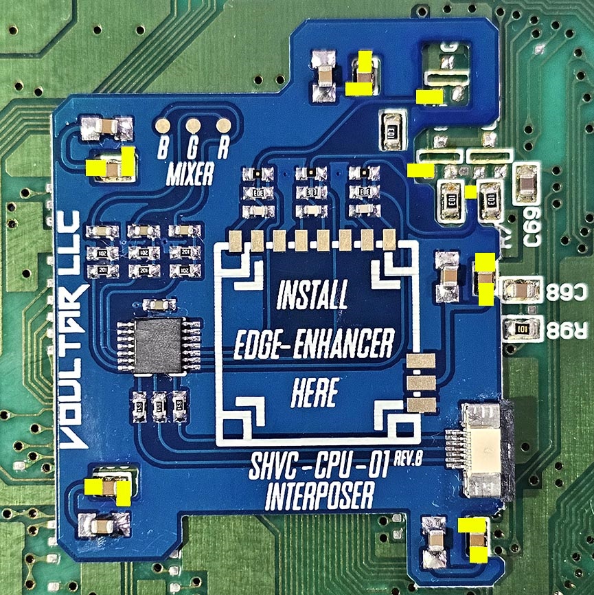
Align the Edge-Enhancer PCB to the the interposer and solder as shown:
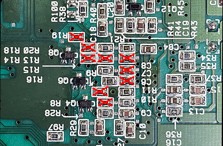
We'll be working in the area within the yellow box:
Remove the components: R19, R18, R14, R13, R9, R8, C8, C7, and C6.
RGB Mixer
The RGB Mixer drives clean RGB signals back into the video encoder for optimal S-Video and Composite video.
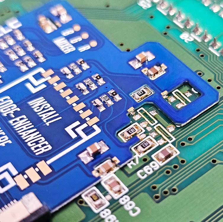
Solder 3 wires to the B, G, and R solder pads SHVC-CPU-01 interposer:

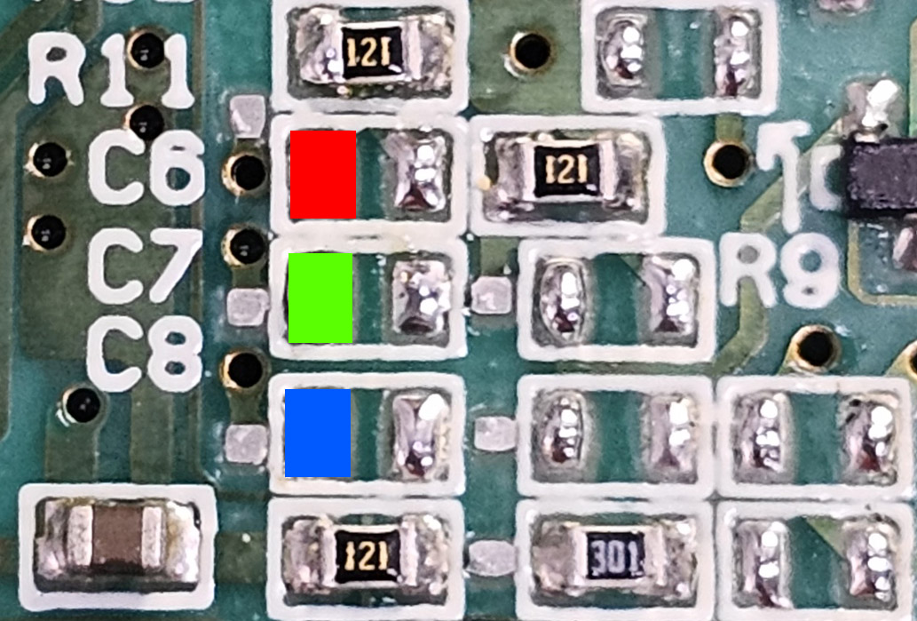
Solder the other side of the 3 wires to the corresponding pads of C8, C7, and C6 that we just removed:
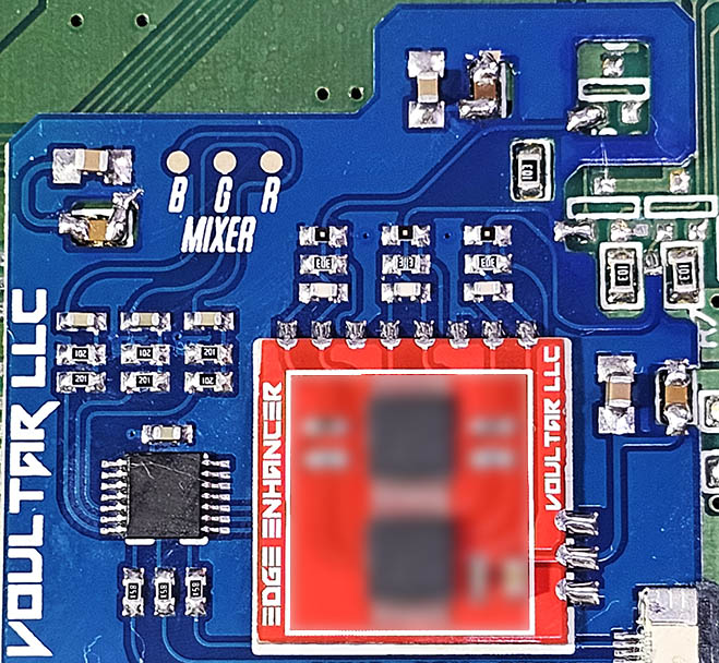
The final result should look similar to this:

When connecting the RGB mixer wires, do not let them come into contact with the cartridge pins. This can cause noise.
Multi-Out QSB
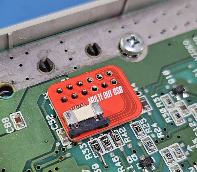
Solder the Multi-Out QSB over the pins of the Multi-Out so that we can connect the interposer directly via an FFC.
Place the QSB into position and solder the 4 vias, skipping the holes:
FFC Ribbon Cable Installation
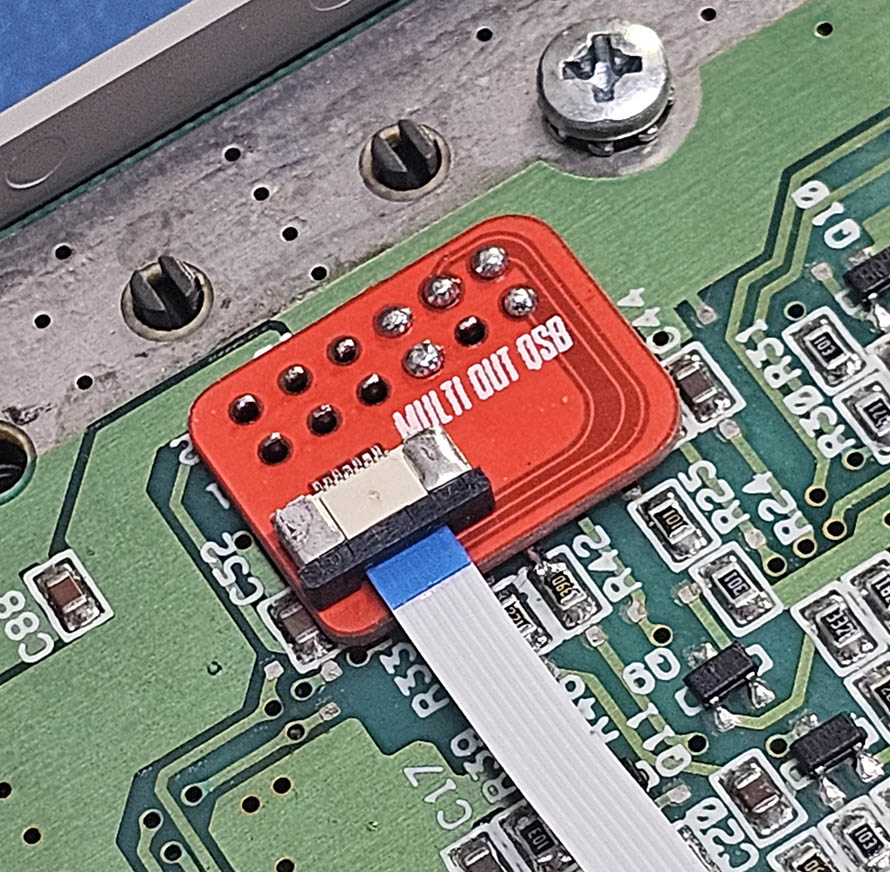
Insert one end of the FFC cable (blue tab upward) into the Multi-Out QSB:
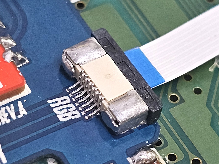
Insert the other end of the FFC cable (blue tab upward) into the interposer:
Finishing Up

This concludes the SNES Edge-Enhancer installation! Be sure to check over your work, test, and finally enjoy!
Troubleshooting
“RGB video isn't working at all!”
- Check over the soldering on the interposer.
- Did you remove all of the components per the instructions?
- Remove and reseat the FFC cable on each end.
“I have RGB video but Composite and S-Video aren't working!”
- Did you remove all of the components per the instructions?
- Check over the soldering on the RGB Mixer connections.
- * The AC coupling capacitors for video could be failing and need replaced.
“My video output is glitchy with weird stripes or artifacts!”
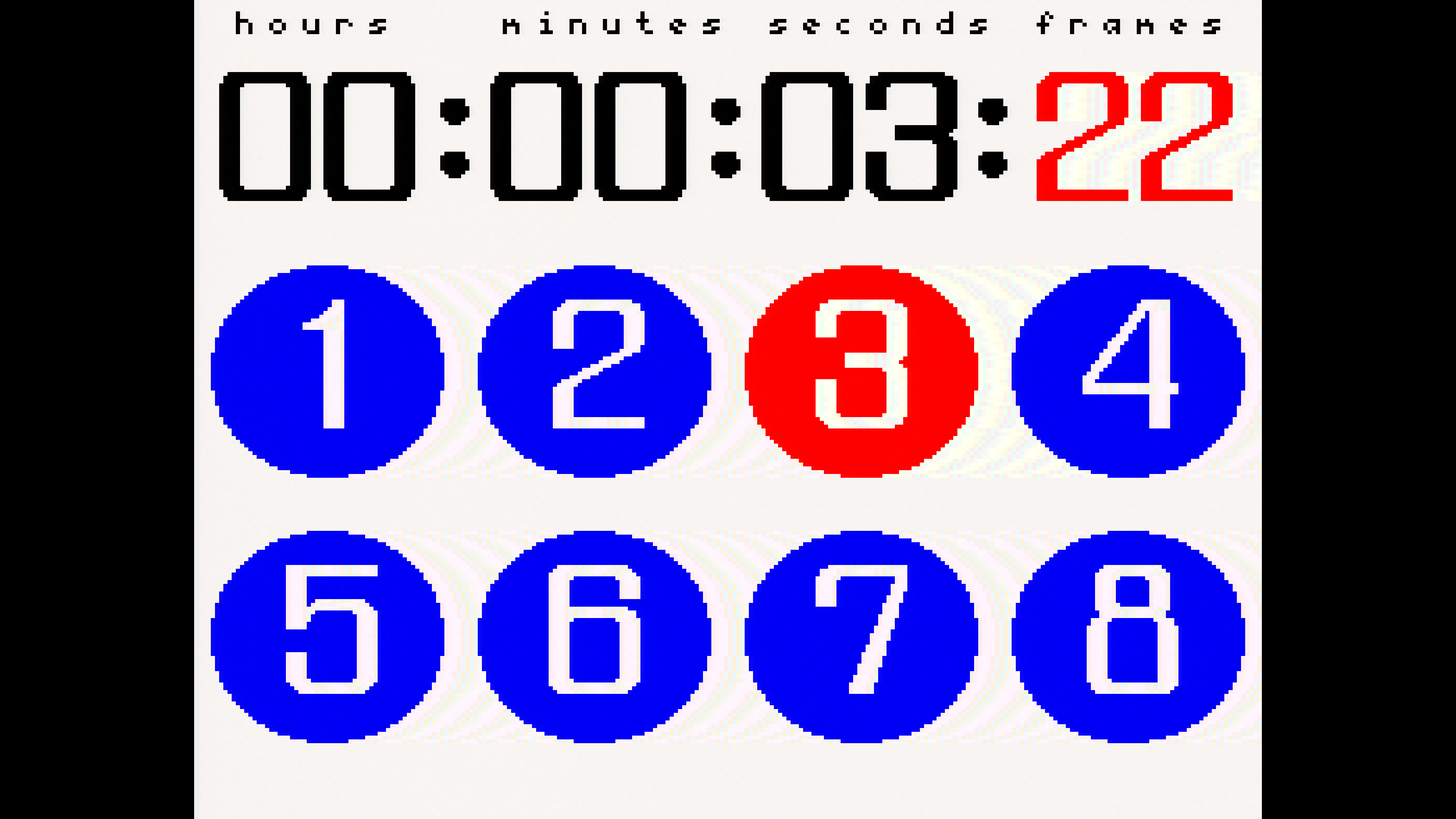
Some SNES PPUs may present with a bug that may cause visual distortions when using the Edge-Enhancer. This is 100% correctable and I have devised a very simple and complete fix for this. The most effective way of determining if you need to apply the fix is to load up the 240P test suite and navigate to the color bar patterns.
Notice the vertical distortions most notably in the cyan and white bars of the 240P test suite:

Here's another example using the lag tester built into the 240 test suite. You can see the distortions in the white areas:
Affected systems can resolve this issue entirely by removing the following 3 components from the interposer:
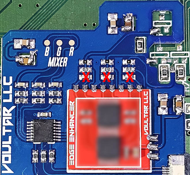
After removal, you'll no longer have any sort of visual anomalies. The fix is complete.
Disclaimer
The information on this website is provided as is without any guarantees or warranty. In association with the product, Voultar LLC makes no warranties of any kind, either expressed or implied, including but not limited to warranties of merchantability, operational failure and/or damage as a result of end-user installation. Use of this documentation by a user is at the user’s risk.