Table of Contents
SNES Cartridge Mods
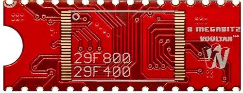
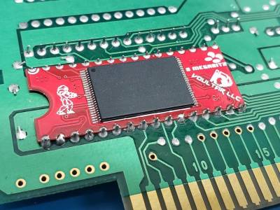
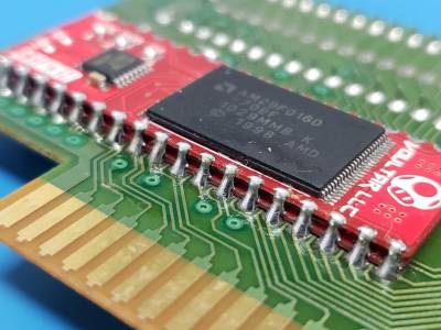
This page will guide you through the procedure of installing the Super Stacker and 8 Megabitz cartridge mods for the SNES. These modules are quite popular as they allow you to translate/convert Super Famicom games without irreparably damaging original cartridges. You can purchase either of these kits from my store.
Follow the directions below and have a great time!
Before We Begin...
These instructions do NOT provide information or instruction that is beyond the scope of the installation procedure. Information concerning ROMs or ROM data manipulation will NOT be covered. It is assumed that the installer is acquainted with programming flash memories and soldering TSSOP48 packages.
The following instructions will only cover the physical installation of Super Stacker and 8 Megabitz. It is assumed that the installer is competent in procedures involving; SNES ROM programming, file manipulation, patching, etc.
Tools Required
- Soldering Station
- 3.8mm Game Security Bit
Game PCB Preparation
We must decouple the original MaskROM(s) from the bus by isolating the /OE signal of the MaskROM(s) and invoke a high logic state to the /OE pin(s).
“Okay, what the hell does that mean?”
It means that we can install our modules onto the cartridge PCB without removing the existing MaskROM(s). When we disconnect the /OE (output enable) pin(s) and tie those signals “high” (which is +5V), we are putting the existing MaskROM(s) into a high impedance state. Effectively, this decouples the MaskROM(s) from the SNES's bus yielding them invisible to the hardware without removing/desoldering anything from the cartridge PCB.
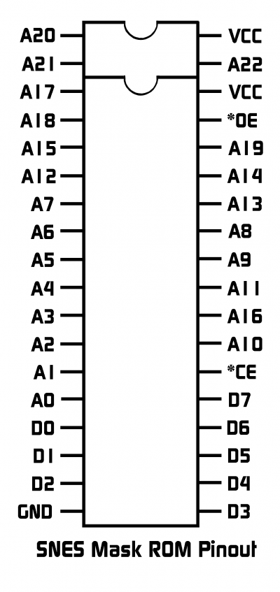
SNES Mask ROM Pinout
MaskROM Preparation Steps
This procedure is the same for all 32 pin and 36 pin MaskROMS. Pin 31 (/OE) will always be lifted and tied to pin 32 (VCC).
- Isolate /OE (pin 31) by either clipping it or heating the pin, out-of-circuit.
- Tie /OE (pin 31) “high” by connecting it (solder bridge) to VCC (pin 32).
Module Fitment
Remember, the MaskROM pins are mirrored because we are working with the backside of the PCB!
Pay close attention to the white half-circle location on the module as this indicates pin 1.
- Flip the cartridge PCB with the backside of the MaskROM pins facing you.
- Align the Super Stacker/8 Megabitz module to the MaskROM's backside pins.
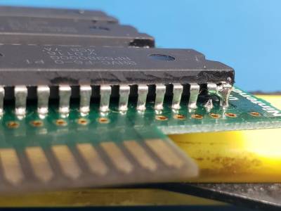
- Ensure that alignment/orientation is correct and solder the module into place.
This is the final step of the 8 Megabitz module installation. To install the Super Stacker, continue reading.
Super Stacker (Single Mode)
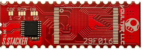
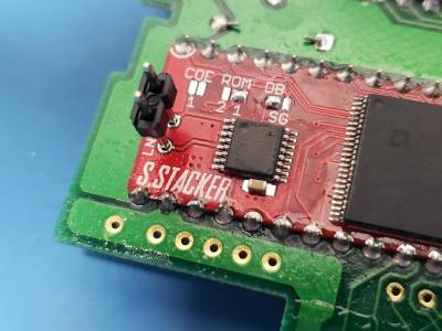
The Super Stacker is a 16 megabit module that's capable of scaling up to a capacity of 32 megabits via “stacking” two Super Stacker modules on top of one another. There are 3 different jumpers that must be set based on the method and/or application.
Setting Jumpers
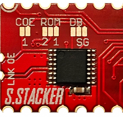
If the Super Stacker is being installed onto a PCB that has either one 34 pin MaskROM or two or more 34 pin MaskRom(s), here are the jumper settings:
- COE - This jumper is always open when not being used in “stacker” mode.
- ROM1/2 - This jumper is always set to “1” when not being used in “stacker mode.
- DB/SG - This jumper is always set to “SG” when not being used in “stacker” mode.
Stacker Mode
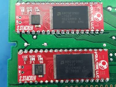
When installing the Super Stacker onto a cartridge PCB that has a single 36 pin MaskRom, “stacker” mode can be utilized. Stacker mode allows you to stack Super Stacker modules on top of each other, giving you 32 Megabits of capacity. We'll now cover the jumper settings and special installation instructions to utilize this mode.
ROM1 Prep and Jumpers
- COE - This is set to “open” on ROM 1.
- ROM 1/2 - This is set to “1” on ROM 1.
- DB/SG - This is set to “DB” on ROM 1.
The PCB has been updated.
“OE” and “LINK” are now castellated edges that can be solder-bridged between ROM1 and ROM2.
ROM2 Stack & Solder
Carefully look over ROM1 before installing ROM2 as you'll no longer have access!
Stack ROM2 over ROM1 and solder the modules. Solder bridge “OE” and “LINK” between both Super Stacker PCBS.
ROM2 Jumper Settings
Set the jumpers for the “stacked” ROM2 accordingly.
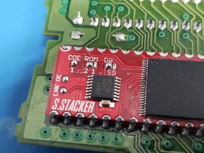
- COE - This is set to “closed” on ROM2
- ROM 1/2 - This is set to “2” on ROM2
- DB/SG - This is set to “DB” on ROM2
Finishing Up
Check over your soldering and ensure that there are no bridges on your modules or memory chips. Clean the PCB of any residual flux and test your cartridge before reassembling.
This is a great time to replace the CR-2032 battery in your cart!
Disclaimer
The information on this website is provided as is without any guarantees or warranty. In association with the product, Voultar LLC makes no warranties of any kind, either expressed or implied, including but not limited to warranties of merchantability, operational failure and/or damage as a result of end-user installation. Use of this documentation by a user is at the user’s risk.
