Table of Contents
SNS-APU-0X Edge-Enhancer Installation
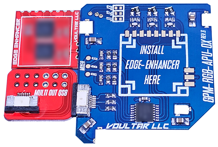
This page will guide you through the procedure of installing the SNES Edge-Enhancer kit into the SNS-APU-01(2) SNES/SFC revisions using the basic method. The SNES Edge Enhancer is an edge correction modification that “deblurs” the video output, yielding much sharper pixels without sacrificing video quality. The SNES Edge-Enhancer is also a dedicated video recovery appliance that preserves and improves all video outputs. Electrically, the Super Famicom is identical to the SNES, making these instructions applicable to the NTSC-J (Japan) equivalent. You can purchase the SNES Edge-Enhancer kit from TBD.
Follow the directions below and have a great time modding!
Materials Required
- Soldering Station
- Hot Air Rework Station (optional)
- Phillips Screwdriver
- 4.5mm Game Security Bit
- 26-28AWG Stranded Wire
Disassembly
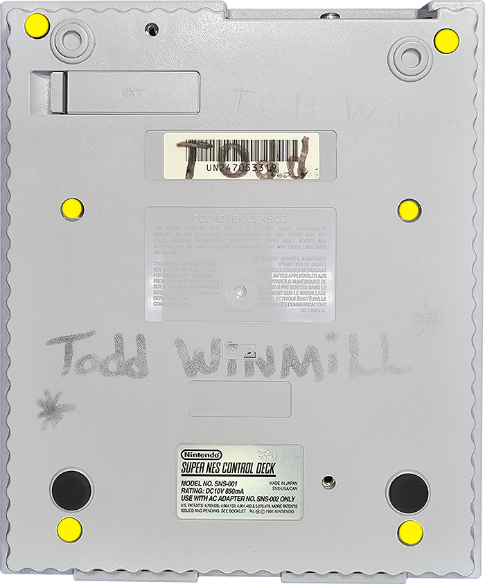
Flip the console over and extract the (6) 4.5mm game-bit security screws. Remove the top shell.
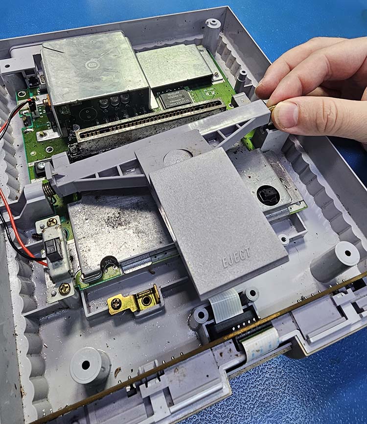
Turn the power switch on to de-energize the system and then remove these 2 screws.
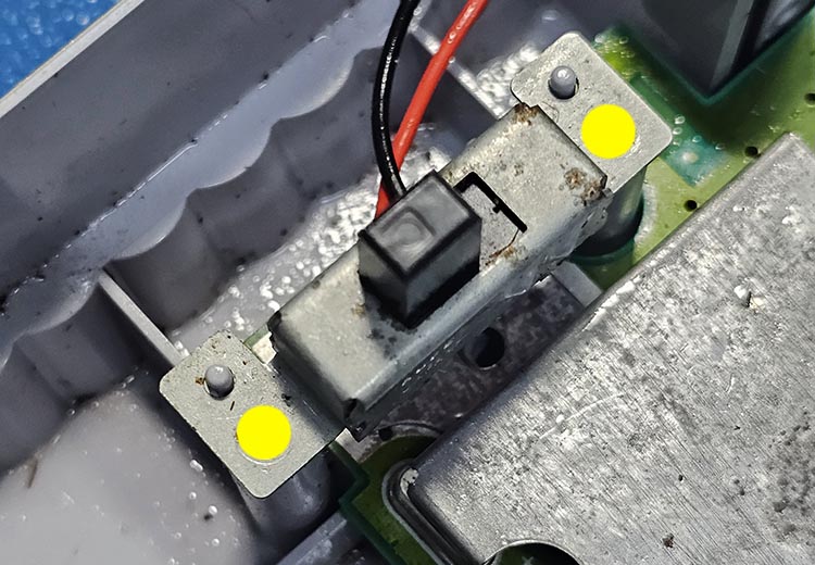
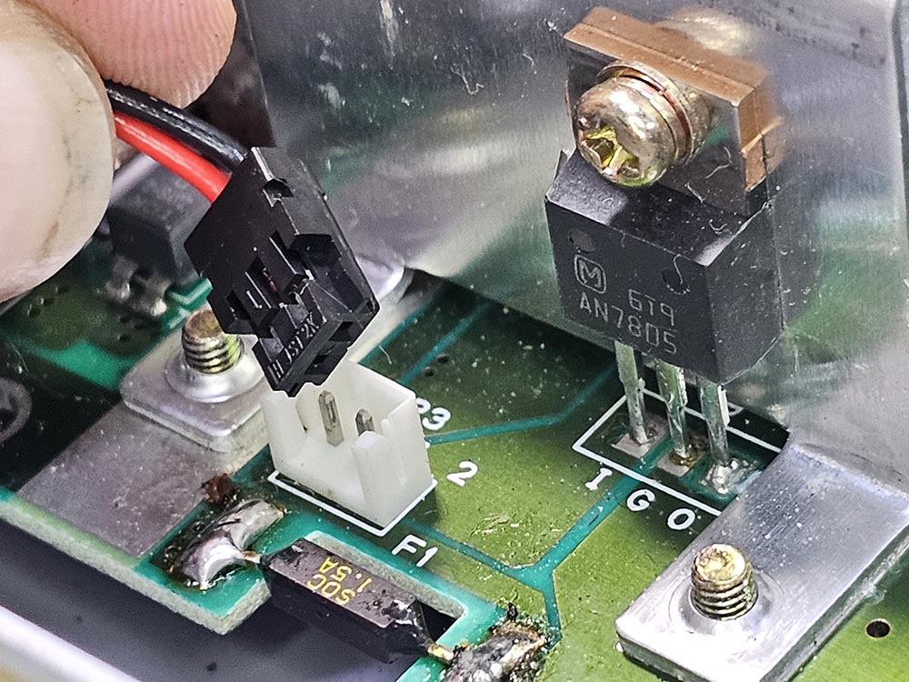
Unplug the power switch loom from the SNES mainboard.
Carefully lift the metal rod and pull away to decouple the eject mechanism. Watch the spring!
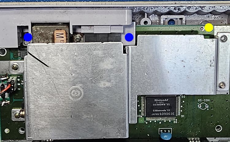
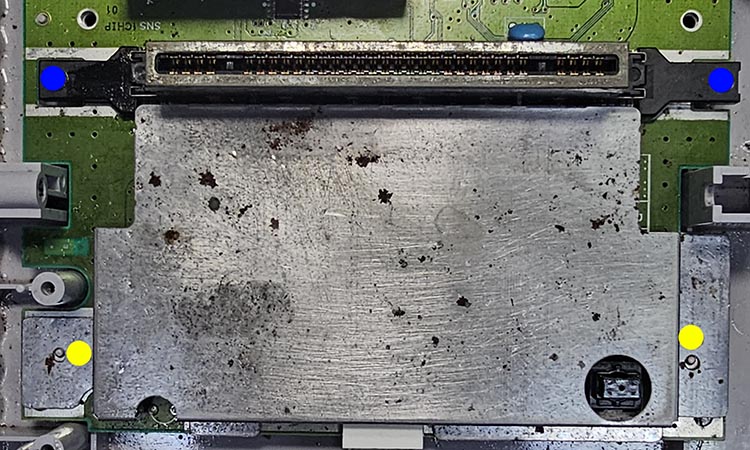
Remove all of the screws marked in yellow and blue to extract the mainboard.
Don't mix up the screws marked in blue with those marked in yellow!
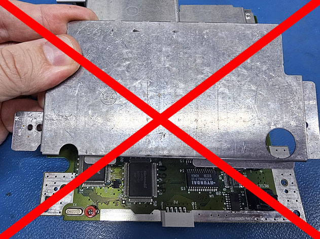
Do NOT reinstall the top/bottom RF shielding (not including heatsink) during reassembly. Discard ALL RF shielding and do NOT use them as they generate noise.
SNES Mainboard Preparation
Be sure you're following the directions for your specific mainboard revision!
We'll be working in the area within the yellow box:
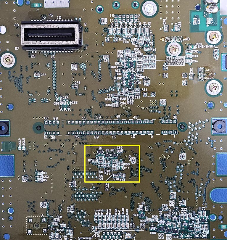
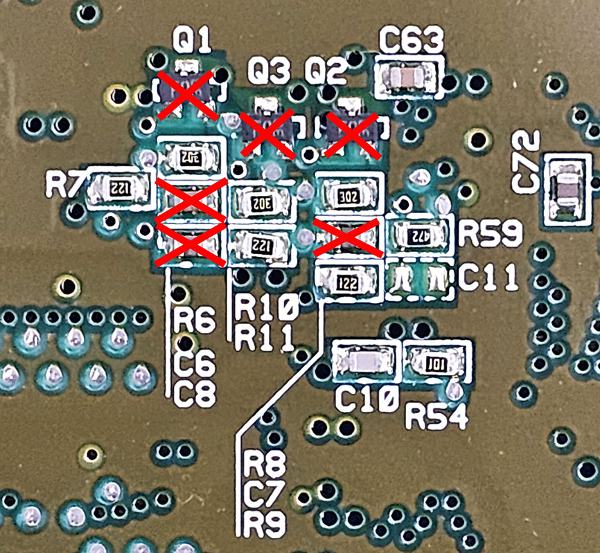
Remove the components: Q1, Q2, Q3, C8, C7, and C6.
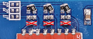
We'll be working in the area within the yellow box:
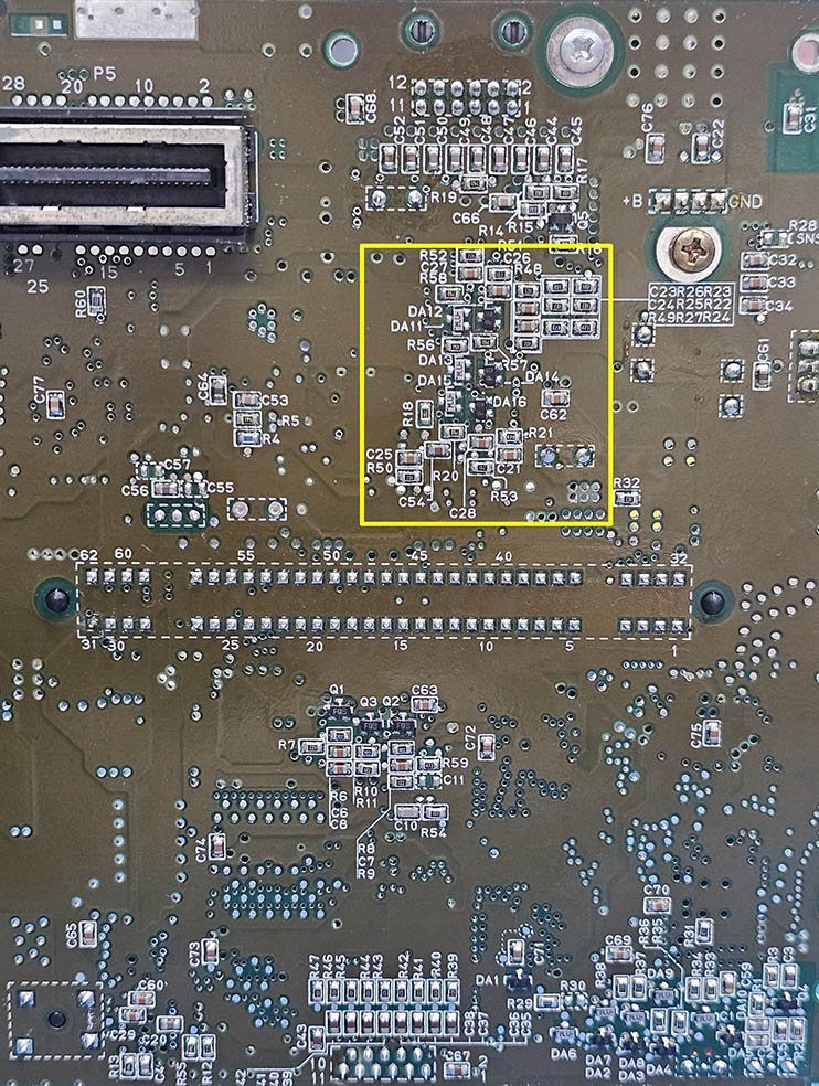
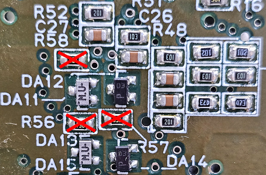
Remove components: R56, R57, and R58.
We'll be working in the area within the yellow box:
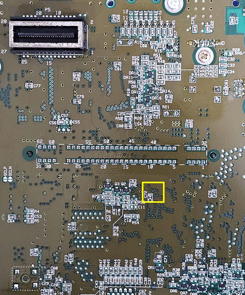
The 3 vias marked in yellow must be exposed by scraping away the solder mask.
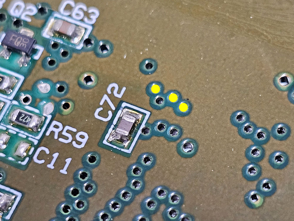
Using a tool such as an x-acto knife, carefully remove the solder mask around the tented vias.
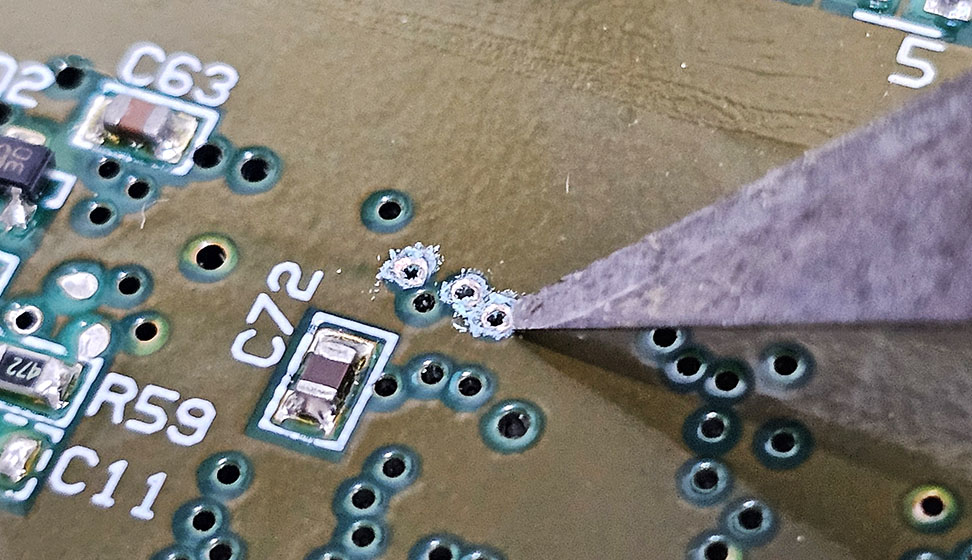
With the vias now exposed, fill each via with solder.
Be VERY gentle when scraping away the solder mask so you don't damage the vias!
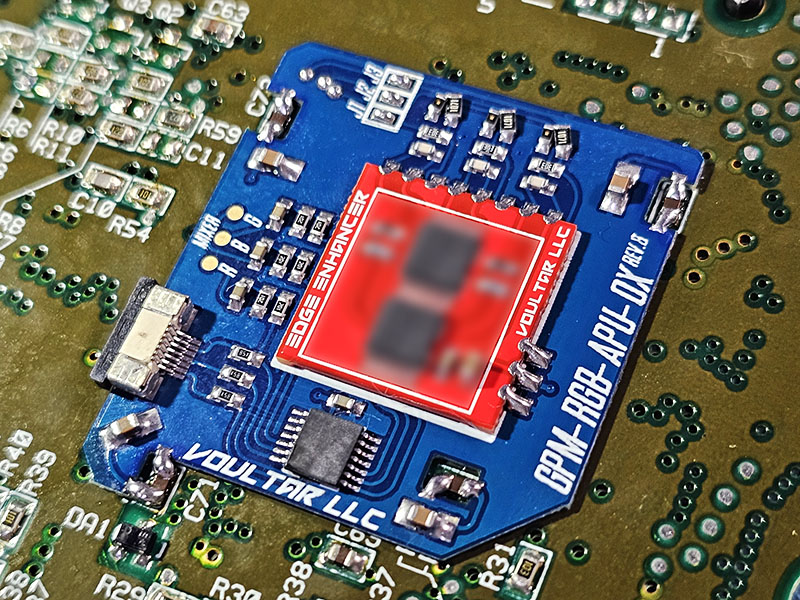
Interposer Alignment
Loosely place the interposer into position.
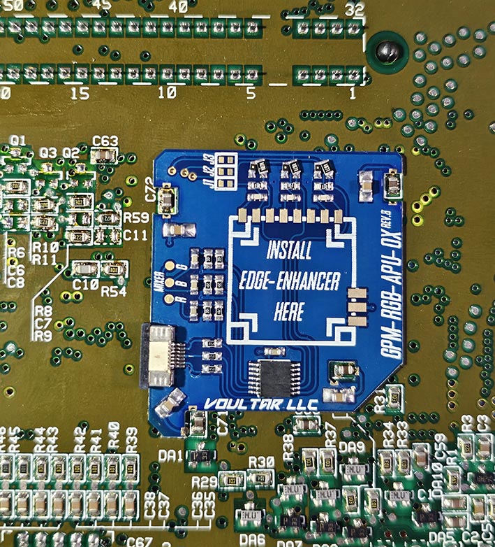
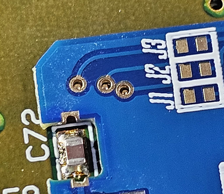
Carefully align the interposer so that the 3 prepped vias can be visualized underneath the interposer as shown:
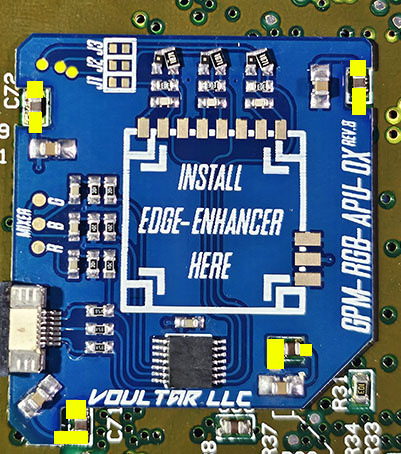
With everything aligned, begin soldering to all areas marked in yellow.
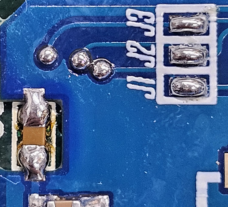
Short jumpers J1, J2, and J3 on the interposer.
Align the red edge-enhancer to the center of the interposer and solder into position.
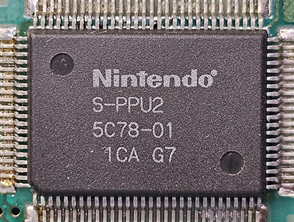
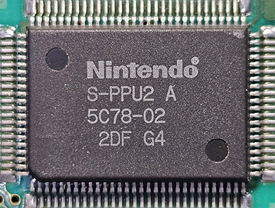
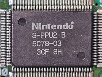
PPU2 Revisions
There are 4 versions of PPU2:
S-PPU2
S-PPU2A
S-PPU2 B
S-PPU2 C
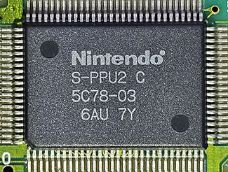
If your SNES has any PPU2 revision other than S-PPU2C, remove the following 3 components from the interposer:
If your SNES has a S-PPU2C revision, do nothing and proceed forward to the RGB Mixer section.
If you don't follow this step properly, the video output from your SNES will be wrong and very distorted!
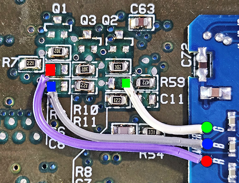
RGB Mixer
The RGB Mixer drives clean RGB signals back into the video encoder for optimal S-Video and Composite video.
Solder 3 wires from the R, B, and G pads of the SNS-APU-0X interposer to: C6, C8, and C7 locations on the SNES mainboard as shown.
Multi-Out QSB & FFC Ribbon Cable Installation
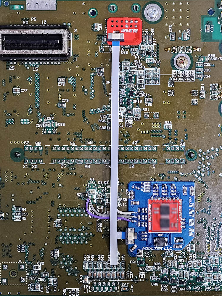
Solder the Multi-Out QSB over the pins of the Multi-Out so that we can connect the interposer directly via an FFC.
Place the QSB into position and solder the 5 vias, skipping the holes. Insert the FFC (blue tab upward).
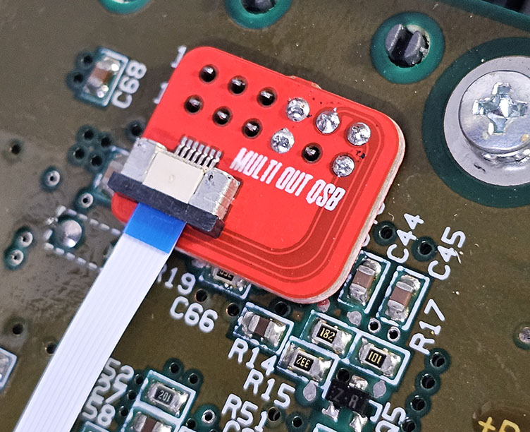
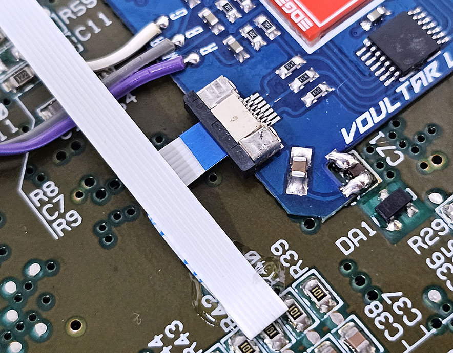
Insert the other end of the FFC cable (blue tab upward) into the interposer and fold the FFC as shown:
Finishing Up
You've finished the “basic” installation of the Edge-Enhancer. Check over your work, test, and finally enjoy!
Troubleshooting
“RGB video isn't working at all!”
- Check over the soldering on the interposer.
- Did you remove all of the components per the instructions?
- Remove and reseat the FFC cable on each end.
“I have RGB video but Composite and S-Video aren't working!”
- Did you remove all of the components per the instructions?
- Check over the soldering on the RGB Mixer connections.
- The AC coupling capacitors for video could be failing and need replaced.
Disclaimer
The information on this website is provided as is without any guarantees or warranty. In association with the product, Voultar LLC makes no warranties of any kind, either expressed or implied, including but not limited to warranties of merchantability, operational failure and/or damage as a result of end-user installation. Use of this documentation by a user is at the user’s risk.